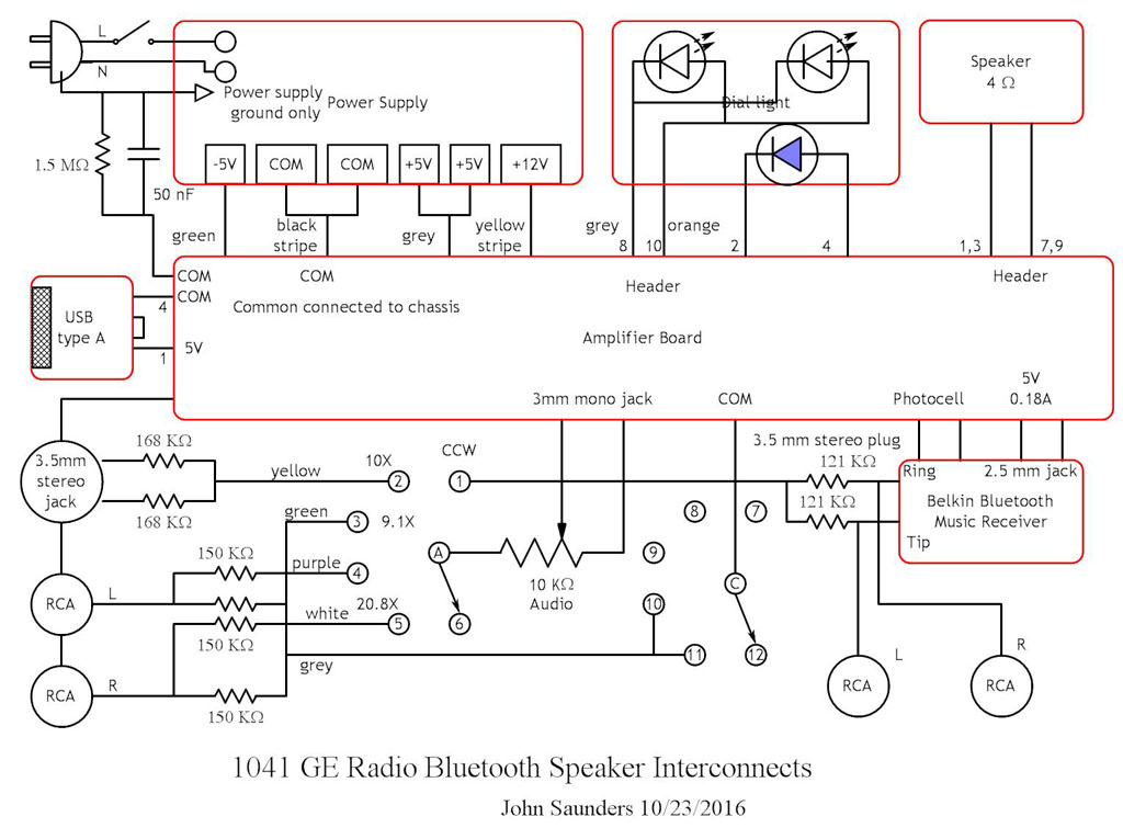
Interconnects
There are four subsystems which can be separated without unsoldering:The Cabinet has attached to it the loudspeaker, the dial LEDs, and the pairing LED. They are all connected to the Amplifier Board by a 10-pin socket and header on the board.
The Chassis contains the power supply, the controls, the hard-wired input connectors, and a circuit board containing attenuator resistors for the hard-wired inputs. The power supply has a 6-pin connector which connects to the Amplifier Board via a pigtail. The chassis has a lead with a 3.5mm mono audio connector which connects to a socket on the Amplifier Board.
The Belkin Bluetooth Music Receiver has a 2.5 mm coax power socket for power, and a 3.5 mm stereo audio connector for its output. The Amplifier Board has a pigtail for its power. The chassis has a pigtail for the audio output. There is also a photocell taped on top of the blue LED. Its lead connects to a 2-pin header on the Amplifier Board.
The Amplifier Board contains the mono audio amplifier and the LED driver which has the photocell for input and the solenoid for output. In addition to the connections listed above, it has a USB type A connector to charge anything which uses 5V. The current capacity is at least 2A. Inputs:
A six-position switch on the right selects the active input source:
1 The Belkin Bluetooth Music Receiver via a stereo to mono attenuator.
2 The 3.5 mm stereo audio jack on the rear of the Chassis via a stereo to mono attenuator.
3 Both RCA jacks on the rear of the Chassis via a stereo to mono attenuator.
4 The middle RCA jack on the rear of the Chassis via an attenuator.
5 The end RCA jack on the rear of the Chassis via an attenuator.
6 Spare.
A second bank on the switch is used to prevent cross-talk between the RCA jacks. The wiper of the selector bank connects to the volume control on the left. Its output goes to the Amplifier Board.
Audio Amplifier
The amplifier circuit is taken directly from the spec sheet of the TDA7240A. It uses 12V from the power supply and provides a maximim undistorted 11.6W RMS sine wave into the 4 ohm speaker. Its -3db frequency response is 25 Hz to 35 KHz.
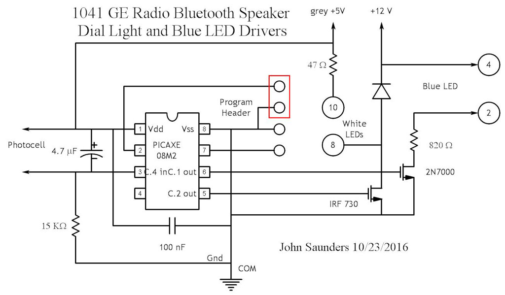
LED Driver
The Photocell input is digitized by a PICAXE 08M2 micro-controller which determines the light/dark thresholds and logic.It can be reprogrammed in circuit via a 4-pin header which connects to an adapter which contains the protection circuits recommended by Revolution Education. Note that a jumper must be used to short the serial input when not connected to the programmer.
There are two MOSFETs for the Dial and pairing LEDs