These are the Dial Clock circuit diagrams.
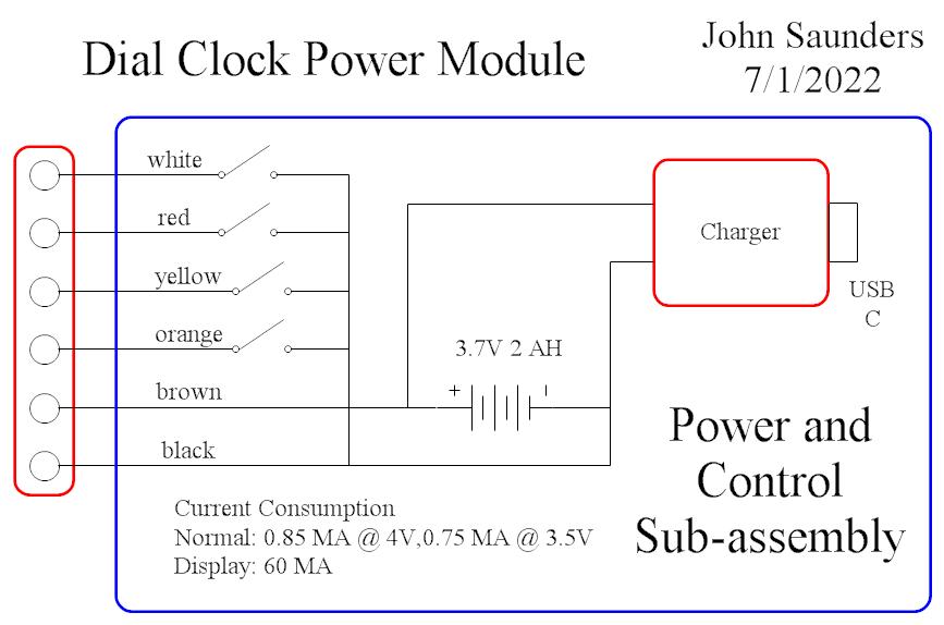
This is the power and push-button assembly.
|
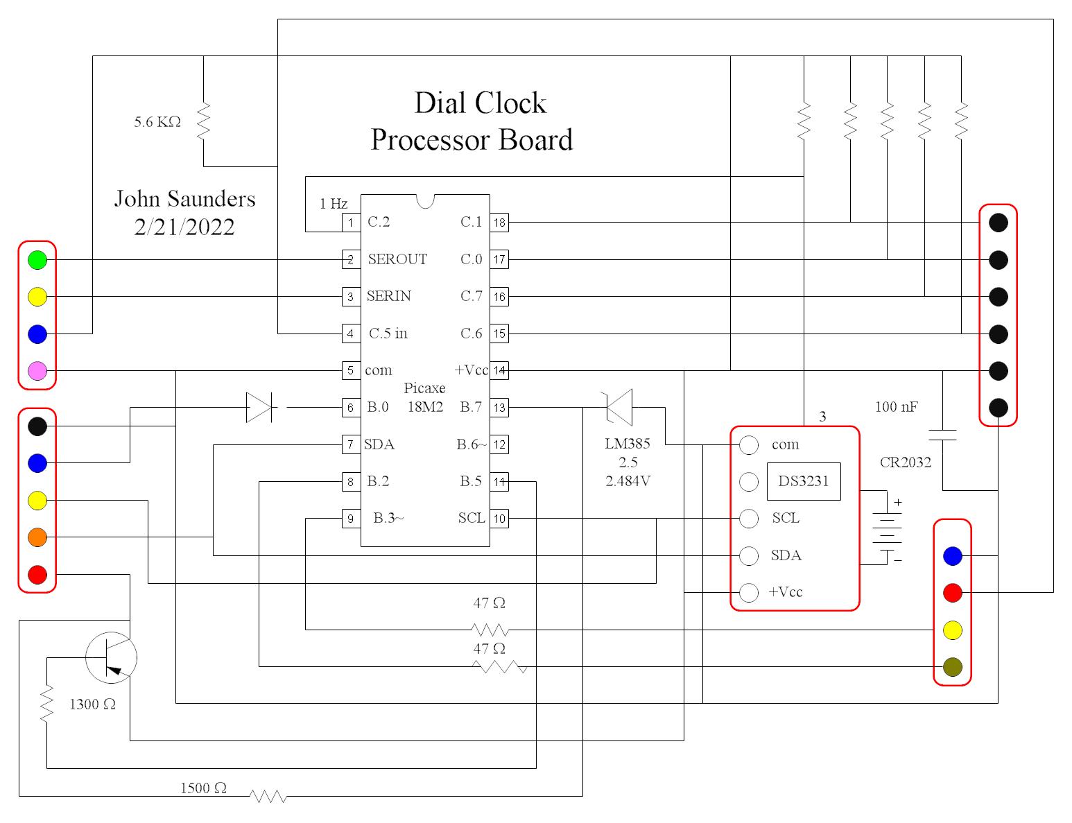
The Processor Board lies under the Display and is in front of the the Transmitter.
|
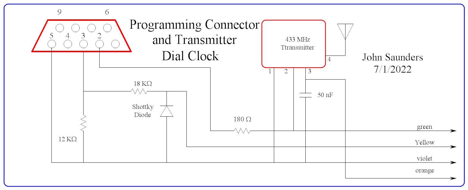
| The Transmitter lies at the back because it includes the programming connector and antenna. It's design is the same as several of my previous projects. It connects to the Processor Board by 4 jumper wires.
|
This character OLED display has a 20-pin header, but only needs 5 because it has I2C protocol selected. Since it is usually off, isolating diodes and a transistor were necessary for the SDA and SCL leads to prevent current leakage from the I2C pullup resistors. It connects to the Processor Board by a 5-pin jumper cable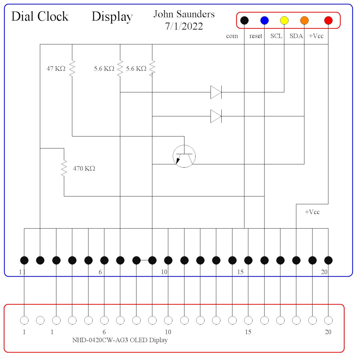 |