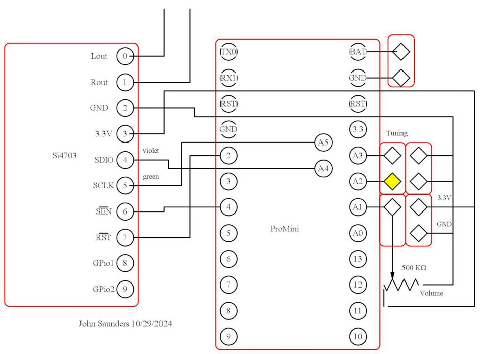
FM Radio Breakout and SparkFun Minipro Arduino .3V 8MHz
These are on the main board which was cut from a full-size Adafruit “Perma-Proto”. This has plated-through holes which greatly ease soldering. The two items had headers soldered to them which plug into receptacles soldered into the board. Since A4 (SDIO) and A5 (SLCK) are not on the board’s grid their headers are soldered on the top. They are connected by jumper cables. Not included in this digram is the -pin programming header which is also soldered on top between Two and BAT. Green is next to BAT.
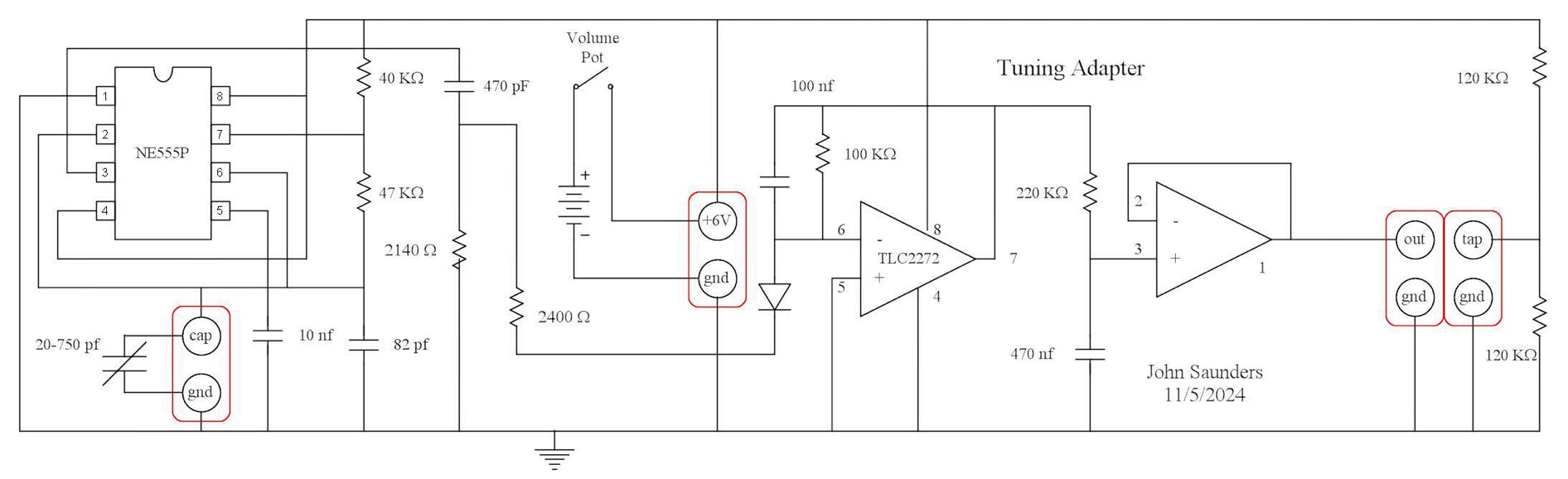
Tuning Capacitor Adapter
These are on a separate board which is connected to the tuning capacitor by two jumper cables and to the min board by five jumper cables. Two are for 6 volt power, and three for the two output signals and another ground cable. One of the signals is a DC voltage which gives the position of the tuning capacitor, The other measures the battery voltage.
The tuning capacitor controls the frequency of a NE555 oscillator between 12 and 70 KHz with a 0.35 - 0.65 duty cycle.waveform. A 82pf padding capacitor makes for a more compatible frequency range.
This output is differentiated to provide a pulse energy independently of the frequency. The negative pulse feeds into the first op-amp, which is an integrator. This produces an average output proportional to frequency. The ripple is attenuated by the second op-amp, which is a low-pass filter.
A half-voltage divider is used for measuring battery voltage. The arduino divides the output voltage measurement by the battery voltage to minimize the effect of battery voltage variation.
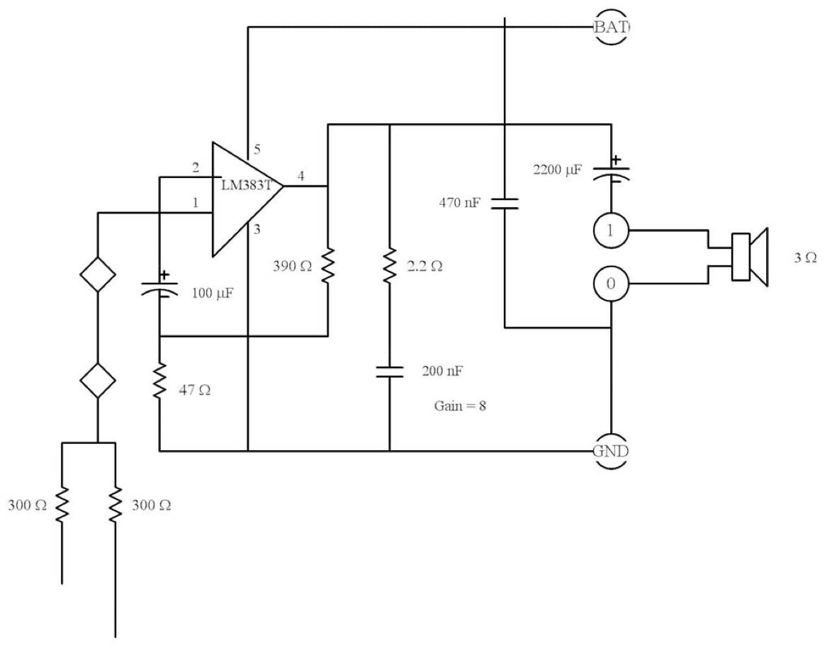
Speaker Amplifier
The outputs of the Si4703 are stereo, and are of line strength, about 800 mv RMS.
These are averaged before amplification by a LM383T, which has feedback for a gain of 8.
Since the LM383T can manage an output of only about 2.5 V p-p, The output volume is usually set low in the Si4703.