|
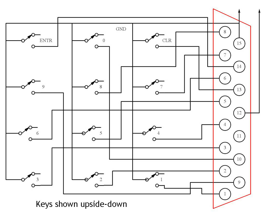
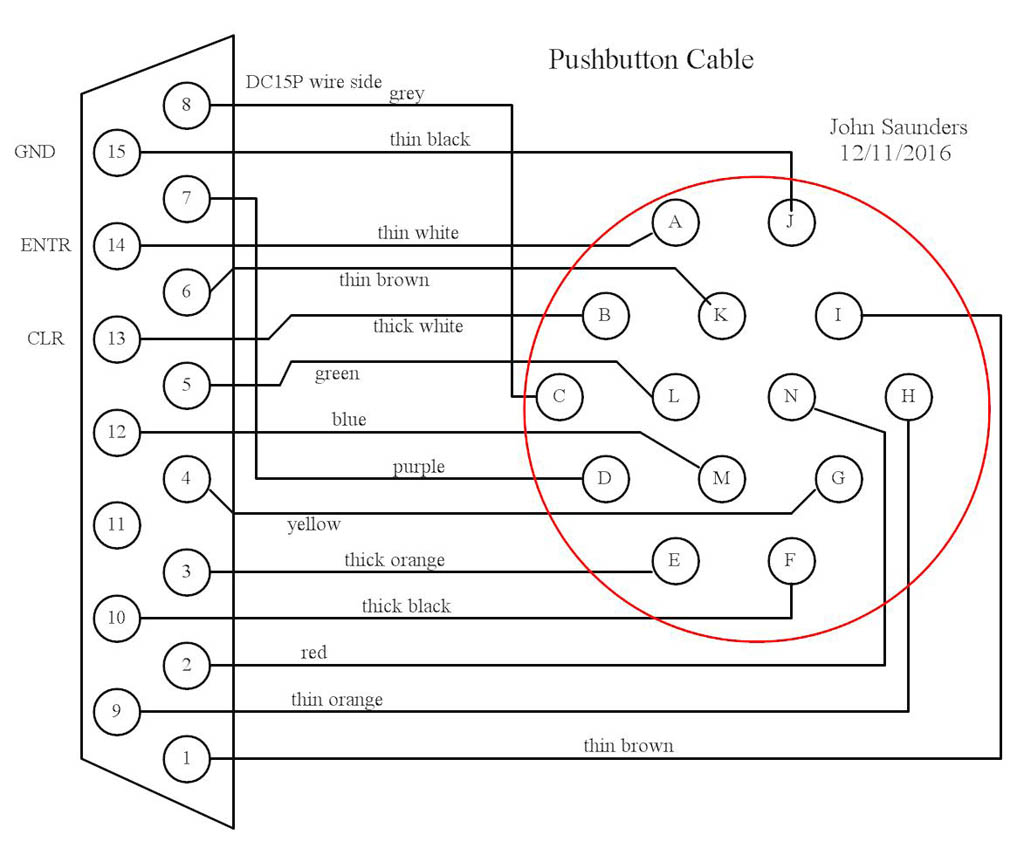
The keypad box is connected to the control box by a 14-wire cable with a DC15P connector at one end and a military circular connector at the other.
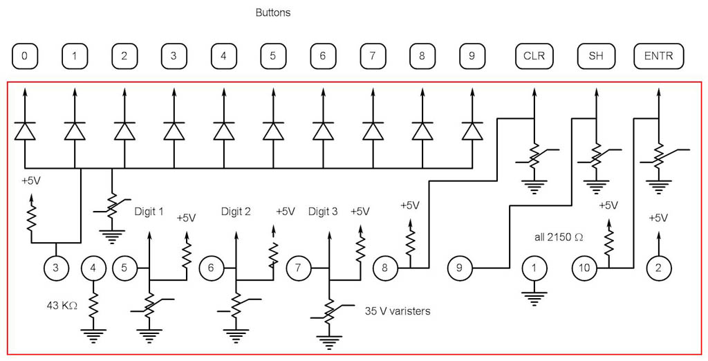
The key wires go both to the thumbwheel switches and the diode board. The thumbwheel switches are BCD with 0-9 positions, so each of the 3 pairs is connected to only 8 of the 10 key wires. A different set is selected for each pair. These switches are only set to 1,2,4 or 8 to get a unique connection. One of the two switches of each pair, but not both, will be set to zero.
The diode board uses 10 diodes on the 10 numeric key wires to provide an interrupt to the processor if any numeric key is pressed.
The ENTR and CLR wires go directly to the processor and are also interrupts.
The board includes pullups and static protection for all processor inputs.
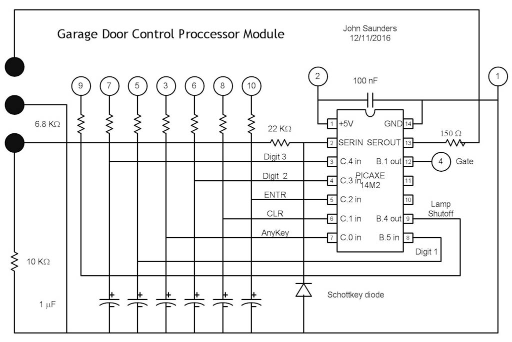
The processor has filtering for all inputs and not much else. It is connected via a 10-pin header. A 3-pin header is included for programming.
|
Keypad
|
|
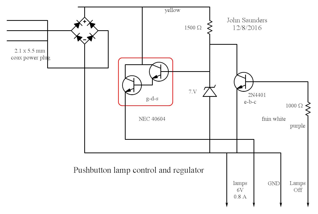
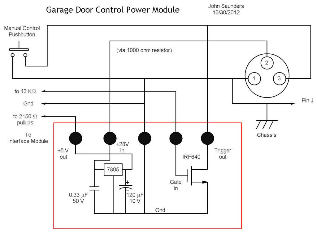
Lamp Control and regulator board
|
|
Cable
|
|
Thumbwheel Switches
|
|
Diode Board
|
|
Power Board
|
|
Processor Board
|