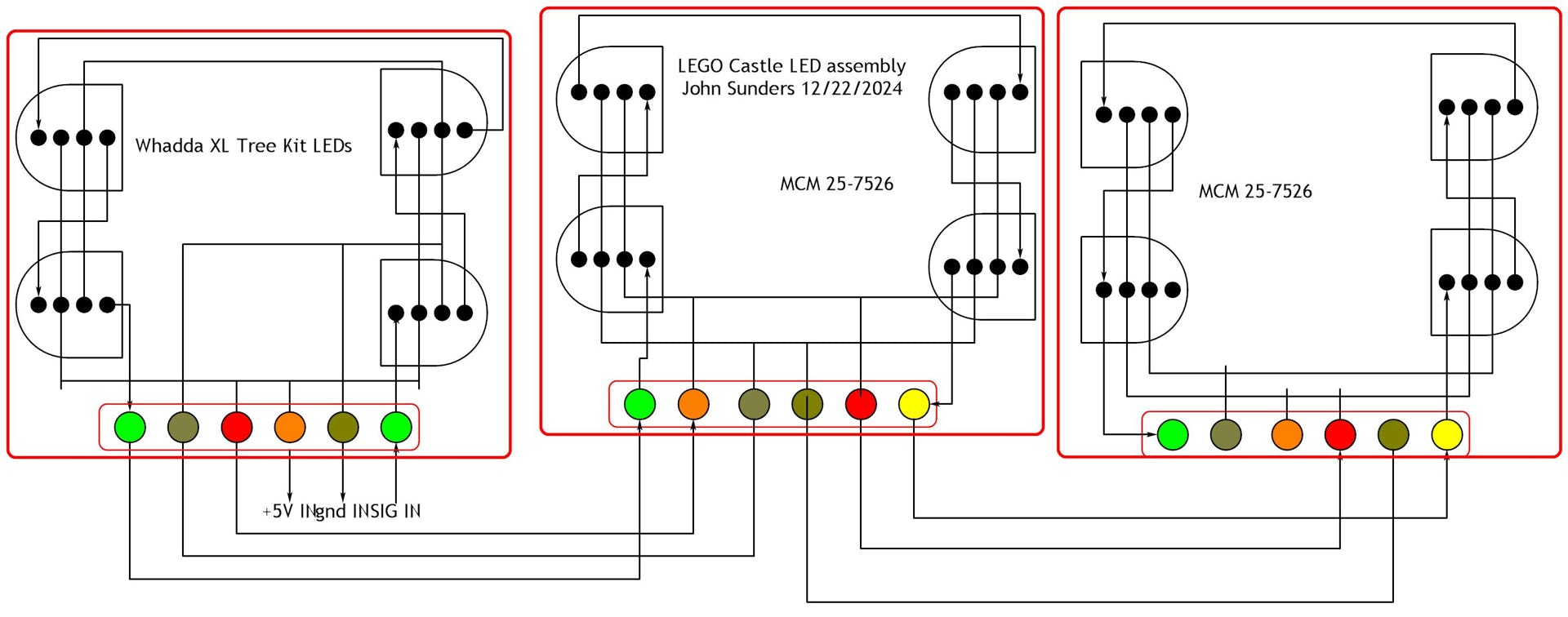
Each LED contains a red, a blue, and a green LED. I think the Whadda chips also have a white LED.
The update bitstream contains a burst for each LED. Each burst has 8 pulses per LED. The Whadda Tree burst has 32 pulses; this project has 24. An IC picks out the first burst and send out the rest to the down stream LED.
The pulse rate is 800 KHz and each pulse contains either a 320 ns or a 860 ns high.
The LEDs are connected in a pi arrangement, clockwise for sides, counter-clockwise in the front, viewed from the outside. First is right side, bottom left. This diagram is from the inside.
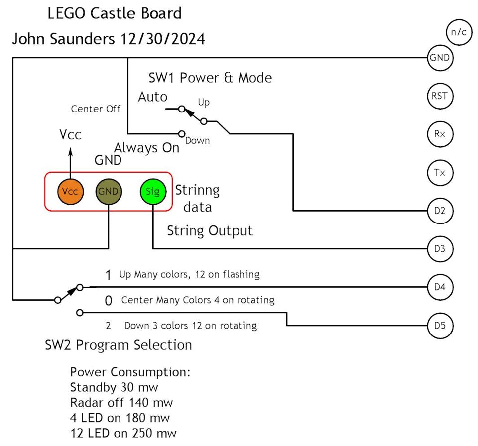
The bottom switch is double-pole 3-way, center off. One pole controls power to the project from a 6V switching wall plug power supply. The other selects using D2 whether the display can be turned on/off by the radar module.
The other switch is single-pole 3-way, center off. It selects one of three display patterns using D4 and D5.
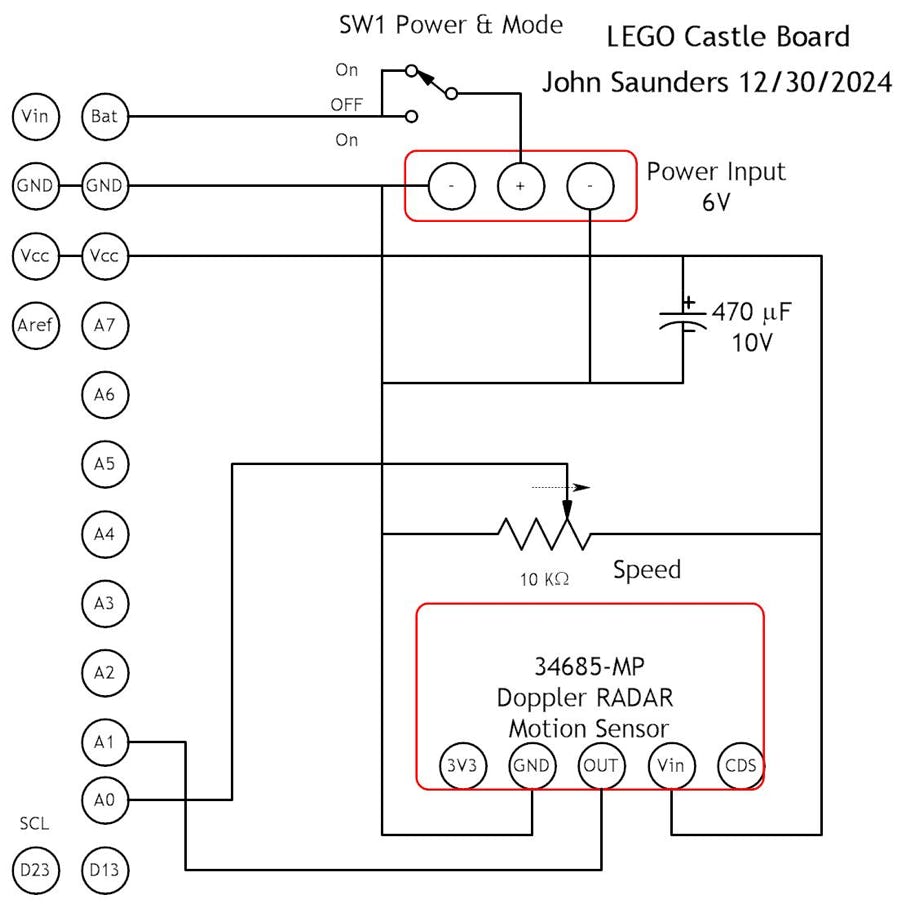
The potentiometer controls the display change rate. It uses A0.
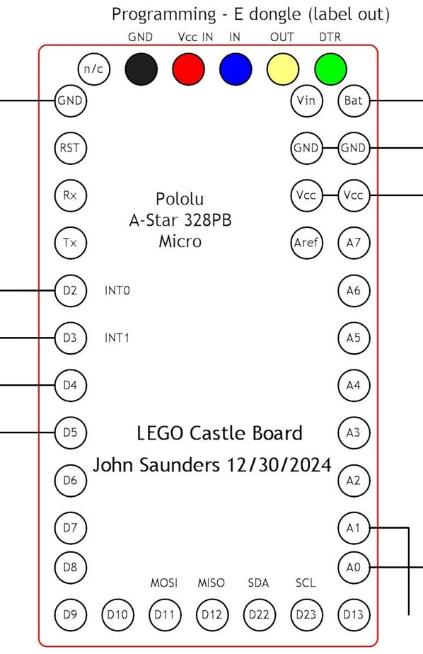
The micro-controller is a uno-compatable Arduino in a micro package. It needs a USB-RS-232 adapter to program it. I use a M CP2104 with an adapter cable which swaps the power connections.
The Doppler radar output is 3V and is sensed by an analog input A1.
The LED output is from D3.