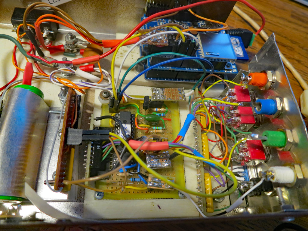
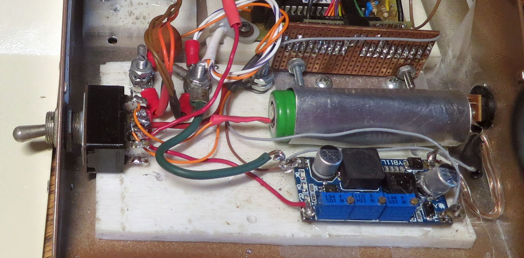
On the top left is a circuit to encode the four arrow buttons into a single analog value to conserve pins on the Arduino, which is hidden below the logger shield.
The board in front of the Picaxe board houses the analog input attenuators.
The other vertical board houses the attenuator for the charging voltage.
The switch cuts off battery power as well as circuit power.
It has an integrate-and-dump circuit to provide an interrupt signal when a message is received. Other parts are for input protection.