Keypad Controller Design
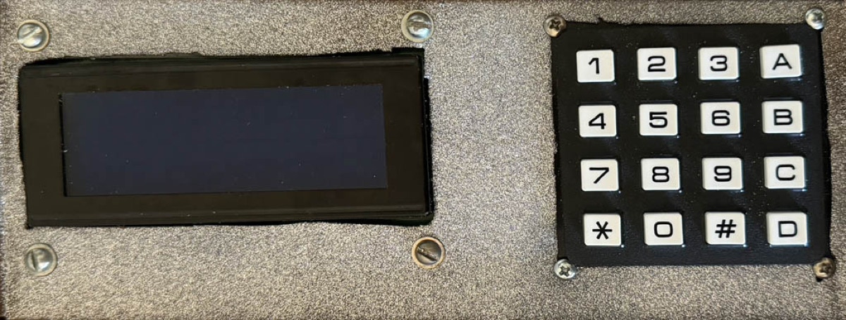
I screwed up badly in designing this project. I had the keypad already as a spare for the garage door controller, so this set a minimum size. I bought a OLEG monochrome graphical display of the same width. Unfortunately the only Arduino library I could find for its uncommon controller took up so much memory that it broke two of the Pololu A-Star processors. I was able to revive only one. I was unable to find a OLED 4-line character display with 0.1” connector, so I settled for a conventional backlit LCD. I bought one cheaply which already had a I2C converter soldered to it. Unfortunately it is wider than the keypad, so it had to go side-by-side.
To minimize soldering and depth the keypad plugs directly into 8 adjacent pins on the processor. Also, to minimize soldering and wires I use an Adafruit “perma-proto” board. This stuck out of the side. I should have cut it short, but I thought it would go under the display, but that turned not to be the case.
So the controller is rather large for a hand-held. I ended up leaving a gap in the emilie for a thumb.
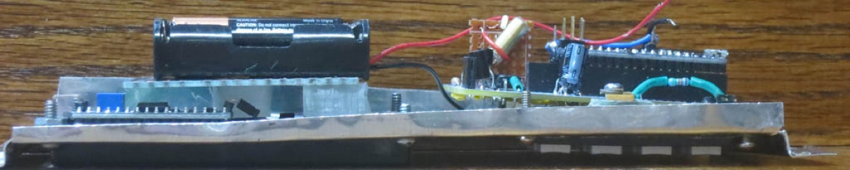
There are 5 parts to this project. The Keyboard, the Processor, the Display, the Battery, and the Transmitter. This aluminum top panel supports all except the Transmitter, which is farmed to the bottom of the wood box. The keypad is fastened to the panel with screws. The processor board plugs into it and is secured bye a latch. The A-Star chip plugs into the processor board, which also contains all of the discrete components and connectors for the Display, the Battery box, and the Transmitter.
The Display is fastened to the panel with screws. The battery box is fastened to a carrier board with mounting tape. This in turn is fastened likewise to the display board.
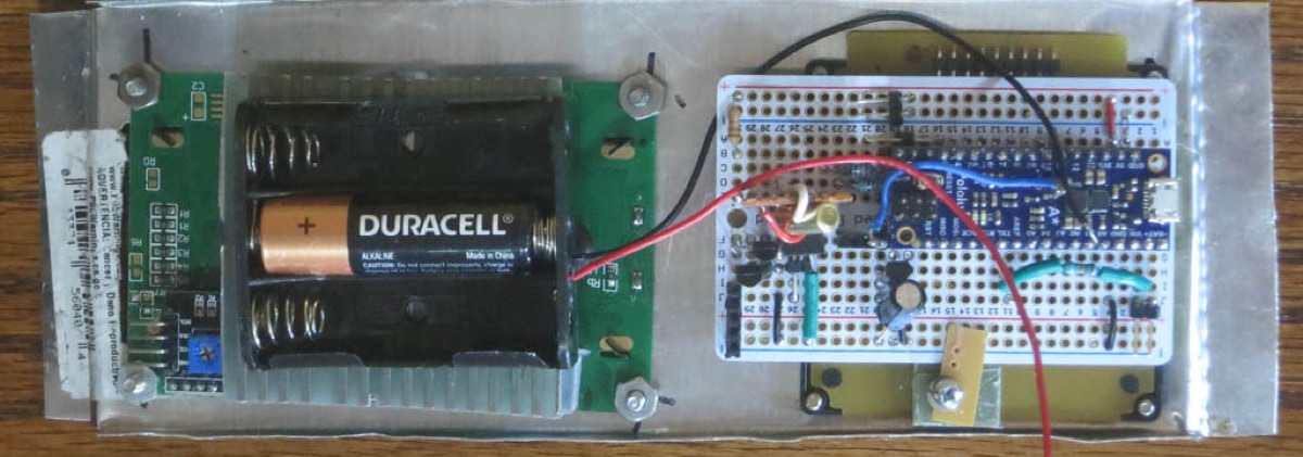
This is a back view of the panel.