Display and Range Switch Circuit Diagrams |
|
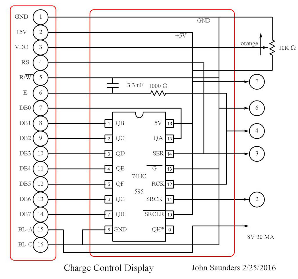
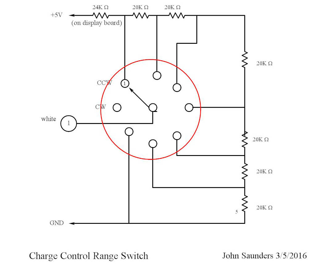
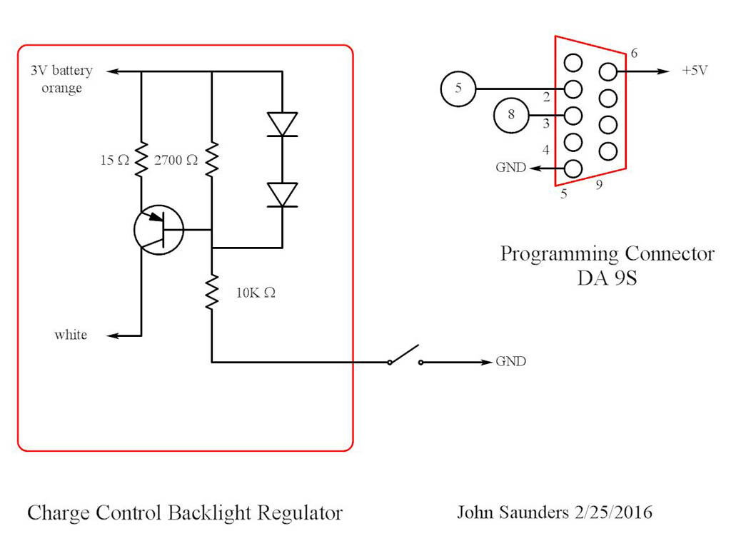
This group of citcuits are attached to the sheet metal and share an 8-pin header connector to the main board. The 2-row by 16 character LCD display module has the common 14-pin connector. This display is connected to a serial-to-parallel shift register in order to reduce the number of wires and for neater software. I usually use the 74H164 shift register fr this, but this time I used the more complex 74H595 because its pinout matches that of the display, so no wiring is needed. (The board is stripline). The shift buffer clock and the display enable can be connected together since they are active on opposite edges of the pulse. This display has LED backlighting, which was a problem since it needed 8 volts, and the battery is 6 volts. I had to add a 2-cell alkaline auxiliary battery and a current-limter circuit with low voltage drop. This is directly connected to the 3-volt battery by a wire. It is controlled by a push-on - push-off button. The range switch also presented a problem since the clockwise position has no contact. A one-megohm resistor to +5V is connected to the switch wiper on the main board to get around this. |
|
|
|
|
|
|