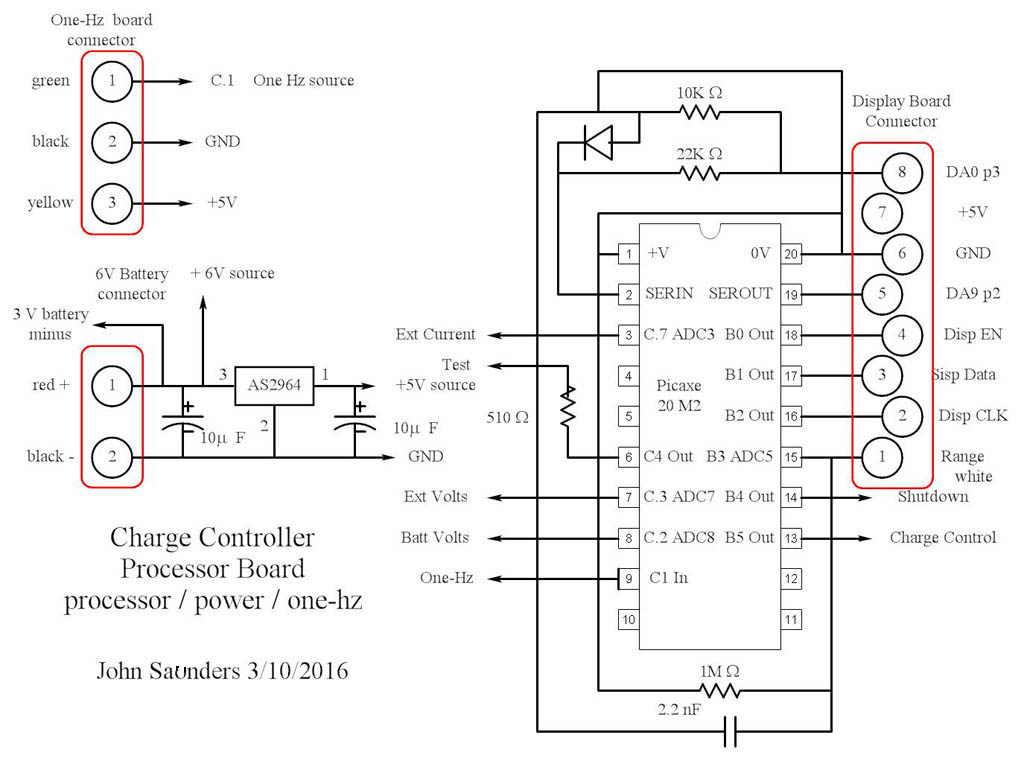
The board has the following connections:
1. An 8-pin header connecting to the Display Board, the Range Switch, and the DA9S programming and transmitting connector.
1. A 3-pin header connecting to the one-second timer.
3. A 2-pin header for the 6-volt rechargable battery.
4. A wire to the negative terminal of the 3-Volt alkaline battery for the backlight boost.
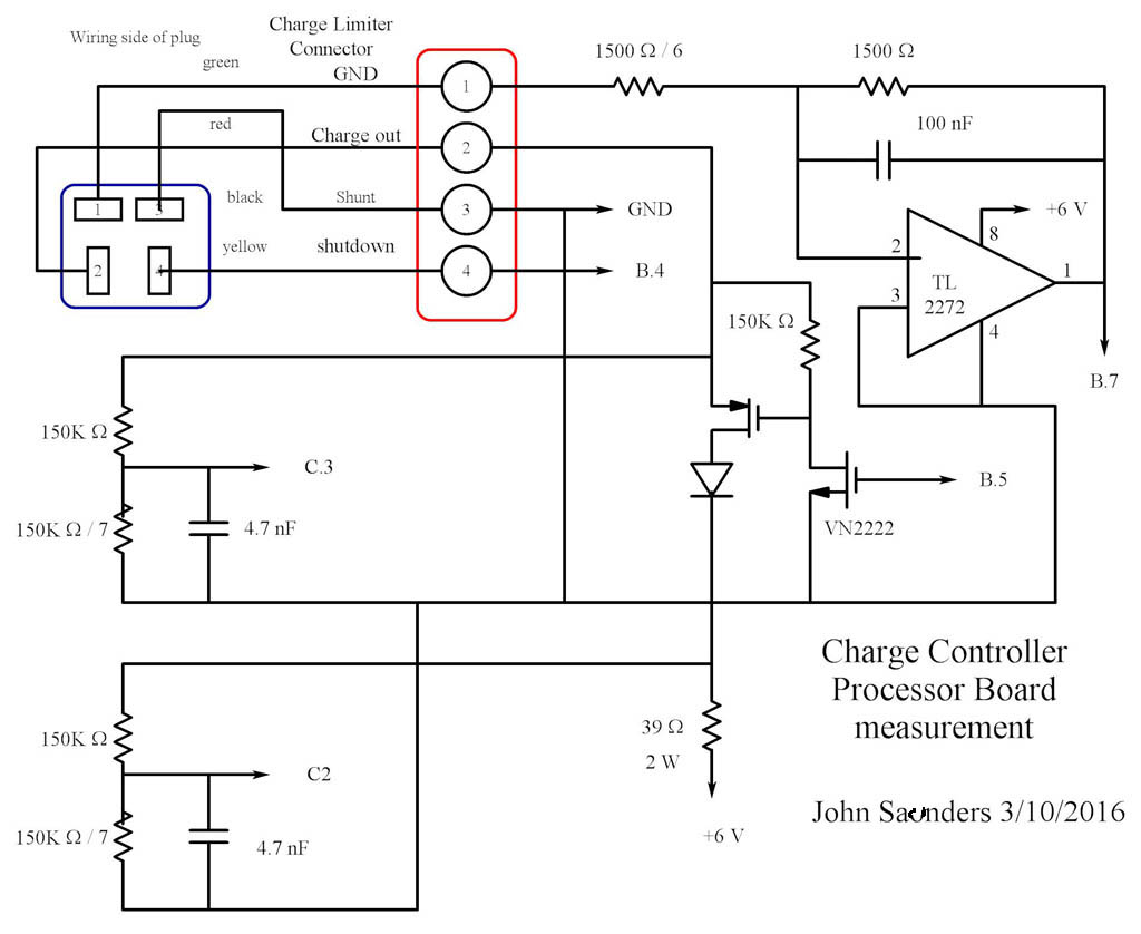
5. A 4-pin header connecting to the Current Limiter.
The Processor has the following outputs:
B.0,B.1,B.2: To the display and its shift register.
B.4: Shutdown to the Current Limiter:
B.5: Charge Control to the 6-volt Battery charge supply.
The Processor has the following inputs:
B.3: From the Range Switch.
C.1: From the One-second timer.
C.2: From a 8:1 voltage divider connected to the 6-volt battery charging resistor. This measures both the battery voltage and the charging voltage.
C.3: From a 8:1 voltage divider connected to the battery being charged.
C.7: From the current amplifier which measures the chargeing current into the battery being charged, via a 1-ohm series resistor inside the Current Limiter. It has a gain of 6.
These are the Processor and Power circuits:
These are the input measurement and internal battery recharge circuits: