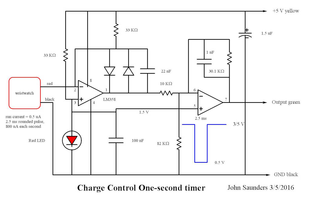
One-second Timer Circuit Diagram |
|
This uses a watch I bought long ago on a trip to Sandpoint. I never used it as it cannot be worn on my wrist and the compass is poor. The watch and its associated board is recycled from my Stepping Motor Clock; a project I consider unsatisfactory because the gears have too much friction. The watch was modified only to remove the battery and solder wires to its contacts. It still keeps time. The watch uses 1.5 V regulated by a red LED and the amplifier provides a virtual low-impedance battery substitute. Every second when the watch moves its second hand it draws a pulse of additional current to rotate its motor. This is amplified to produce a voltage pulse to interrupt the processor. A complication is that while the sheet metal is grounded by the display screws, the adjuster for the watch is connected to its positive battery terminal. When the wheel was pushed in, it contacted the watch case, causing a short circuit. I put an insulating piece of sheet plastic between the watch case and its adjustor, and also insulated the watch case from the sheet metal. Its three wires plug into a header on the Main Board. |
|
|