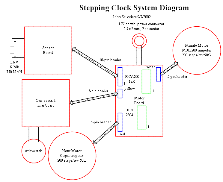
The 12-volt motor supply socket is hard-wired to the Motor Board. All other connections to it plug in to headers. The Sensor Board contains discrete components which would not fit on the Motor Board. It has an accessable 3-pin header for programming. The sole purpose of the Timer Board is to provide a 1-second period pulse.

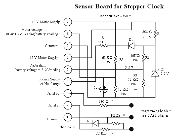
There are four functions to this board. The first is to charge the cordless phone battery which powers the timer and picaxe, which together draw 3 MA. The battery floats at 4V, since it is supplied from the zener. This zener also provides a stable voltage to the picaxe, which is used to compensate for varying battery voltage. This is because pic microcontrollers use their power supply as the reference for their ADCs. The third function is to measure the motor supply voltage to detect power loss. The board also contains the necessary programming interface.

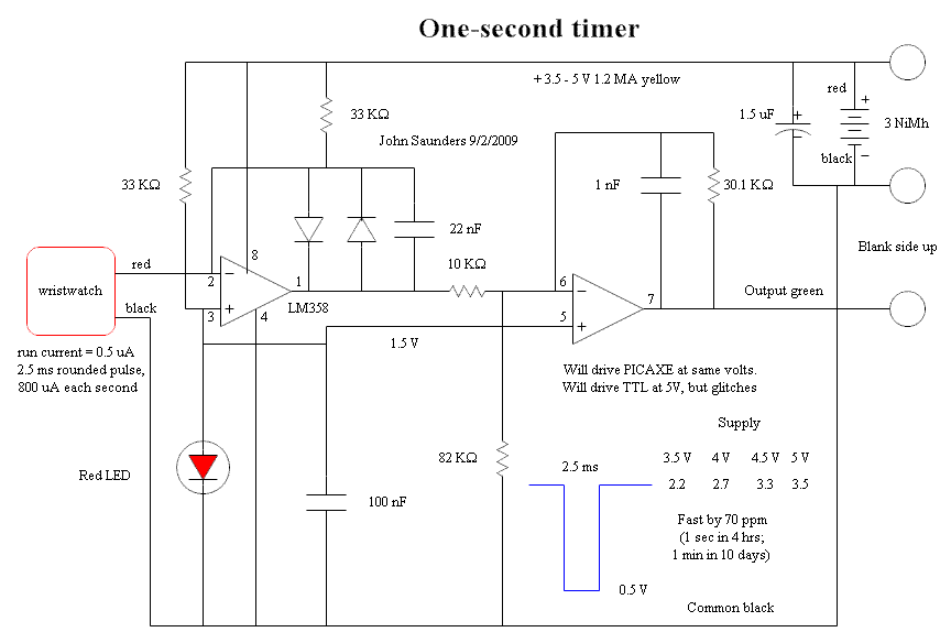
The watch is hard-wired to this board. Its battery is removed and leads soldered to the battery connections. It uses 1.5 volts. A red LED has this voltage drop, and is reference for the op-amps. Feedback of the first op-amp ensures that the watch always has 1.5 volts. Back-to-back diodes keep the op-amp in linear mode and provide a rectangular voltage output. A bleed resistor passes much more current than the watch normally needs, but considerably less than it needs when it is pulsing its motor. The second op-amp amplifies the output. The output is essentially rectangular, but there are glitches which do not affect the picaxe, since it samples.

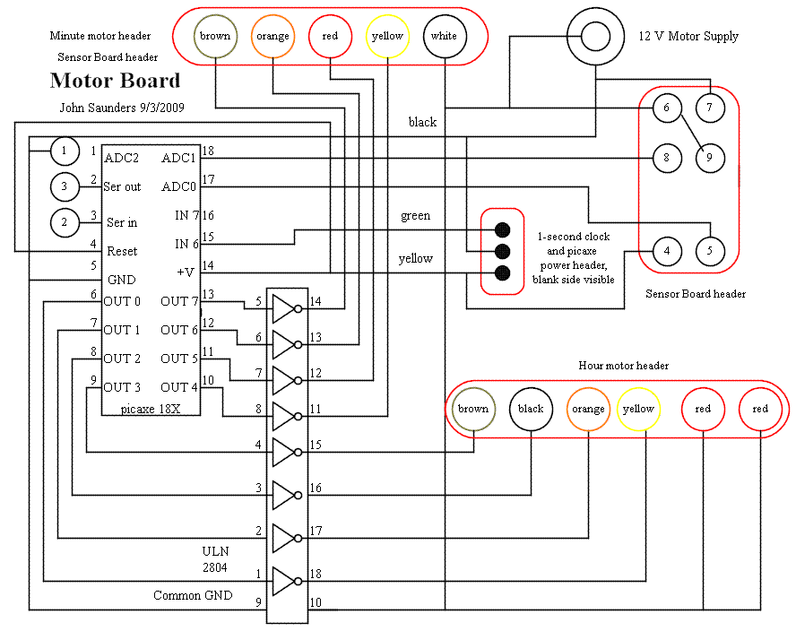
This contains only the picaxe and a ULN2804 octal darlington array. Its pin 10 goes only to diodes to suppress the inductive surge when the motor coils are turned off.