.
Here are the Sensor Board circuit diagrams
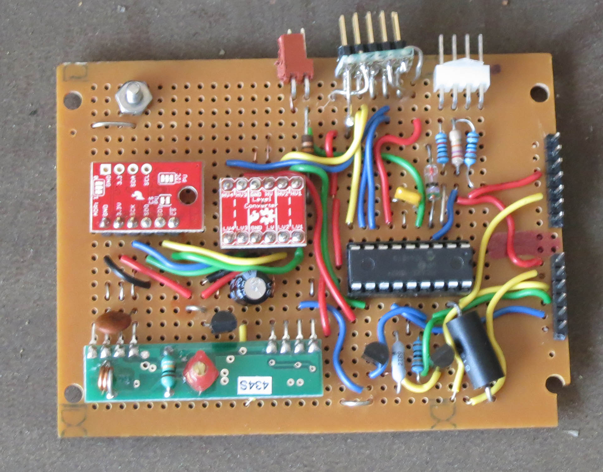
The screw is for the receiver's antenna.
|
|
The Picaxe controller exchanges signals with the sensor and the display using SDI protocol. The Clock and SDO lines are common, but the rest are separate. Note that "SDO" on this schematic is an output from the Picaxe. It is connected to pins marked "SDI" on the sensor and display. Correspondingly thei "SDO" pins go to inputs marked "SDI" on the Picaxe. .
| Here are the Sensor Board circuit diagrams
Here is the Picaxe code | The green object is the 434 MHz receiver. The left red item is the BME-280 sensor. The righr red item is a quadruple bi-directional voltage level converter. It allows the 3.3V sensor to communicate with the 5V Picaxe. The sensor has its own on-board voltage regulator. | The screw is for the receiver's antenna.
|