LED Matrix Clock Home Automation
This is an add-on which is independent of the LED Matrix Clock’s primary function. It provides daily actions which turn on or off devices, or charge their operation mode.
It is the third of my devices for the function. The first is the Alpha LED Clock. This is very flexible since it can be set for hourly, weekly, or monthly repeats, as well as the daily repetitions provided by the other two.The action events are easily programmed using a keyboard. It is limited to 7 entries by the limited battery-backed memory of its RTC.
The second is the Dial Clock. This stores the events in EEPROM, which has a capacity for 48 entries. It is programmed by editing the source code and uploading it. This is routine, but a hassle.
The LED Matrix Clock stores an unlimited number of events in human-readable text files in a micro-SD flash chip. Programming requires removal of the chip, inserting it into a carrier and editing the program files with a text editor, being careful to set it to ASCII-only mode.
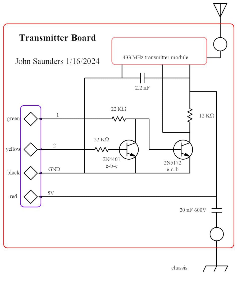
The only added hardware is a RF transmitter, which is shown in the Wiring Diagrams page since the SD drive is part of the Arduino. This is its schematic:

.The transmitter is a Radiotronix 330 MHz module. It is on-off keyed and I have used it in over a dozen other projects. I tried another brand, but it was incompatible. The advantage of using the 330MHz ISM band is that the transmitters and receivers cost under 5$, have good range, and low power. The disadvantage is low bit rate, noise, and other users. However the protocol used has effectively eliminated false positives. Loss is 5-10% so transmissions are mainly duplicated.
The purpose of the transistor circuit is twofold:
1. The transmitter requires an idle-low polarity input signal. Arduinos provide only idle-high and it cannot be changed.
2. A 20-ms pre-pulse is part of the protocol, but digitalWrite() cannot be used on the Tx pin (Pin 1).