LED Matrix Clock Harness
The clock is built on a conventional chassis with the following attachments:
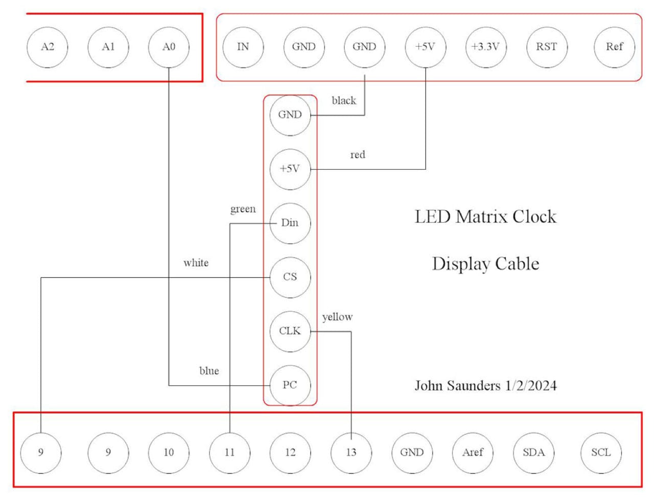
- The display assembly, which includes the photocell and the LIDAR.
- The Arduino, which is an obsolete Ethernet with a micro SD drive. The Ethernet circuit is not used.
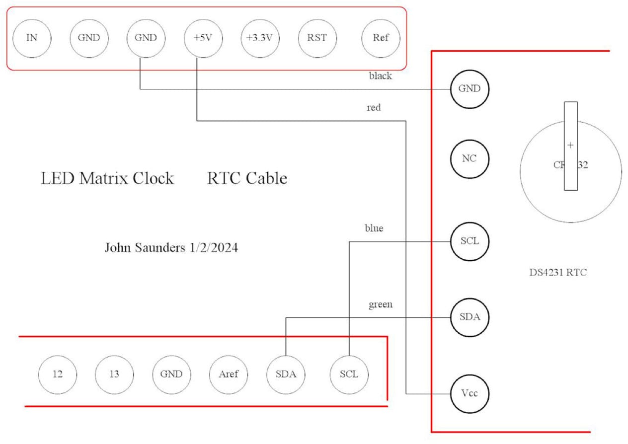
- The RTC, consisting of a DS4231 module and a CR2032 backup battery on a small board.
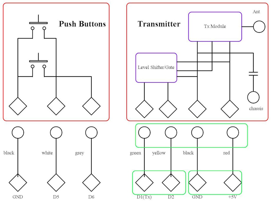
- A sub-assembly supporting the two push-button switches and the RF transmitter,
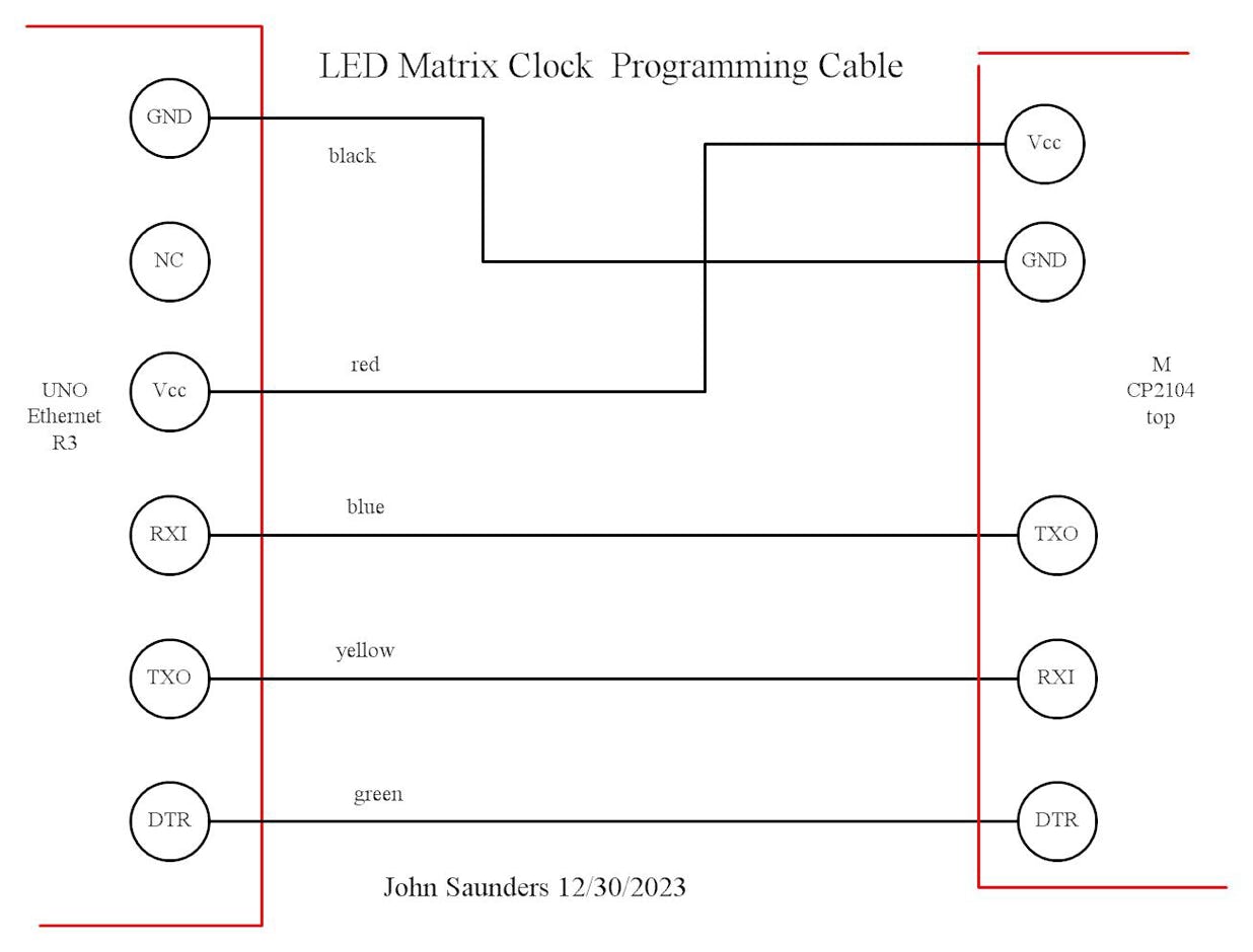
The Arduino is programmed via a standard 6-pin RS-232 connector.
All of these are connected to the Arduino by jumper cables, mostly custom-made.
The clock is powered by a 6.4V switching power module which connects to ground and the Vin of the Arduino,
The wooden box has a metal front panel with a red filter film on it, This is fastened to the box and is not connected to the chassis.
The chassis is secured to the box by a single screw.
The multiple 5v and ground cables are accommodated by a stack which plugs vertically into the Arduino’s two ground and 5V sockets.